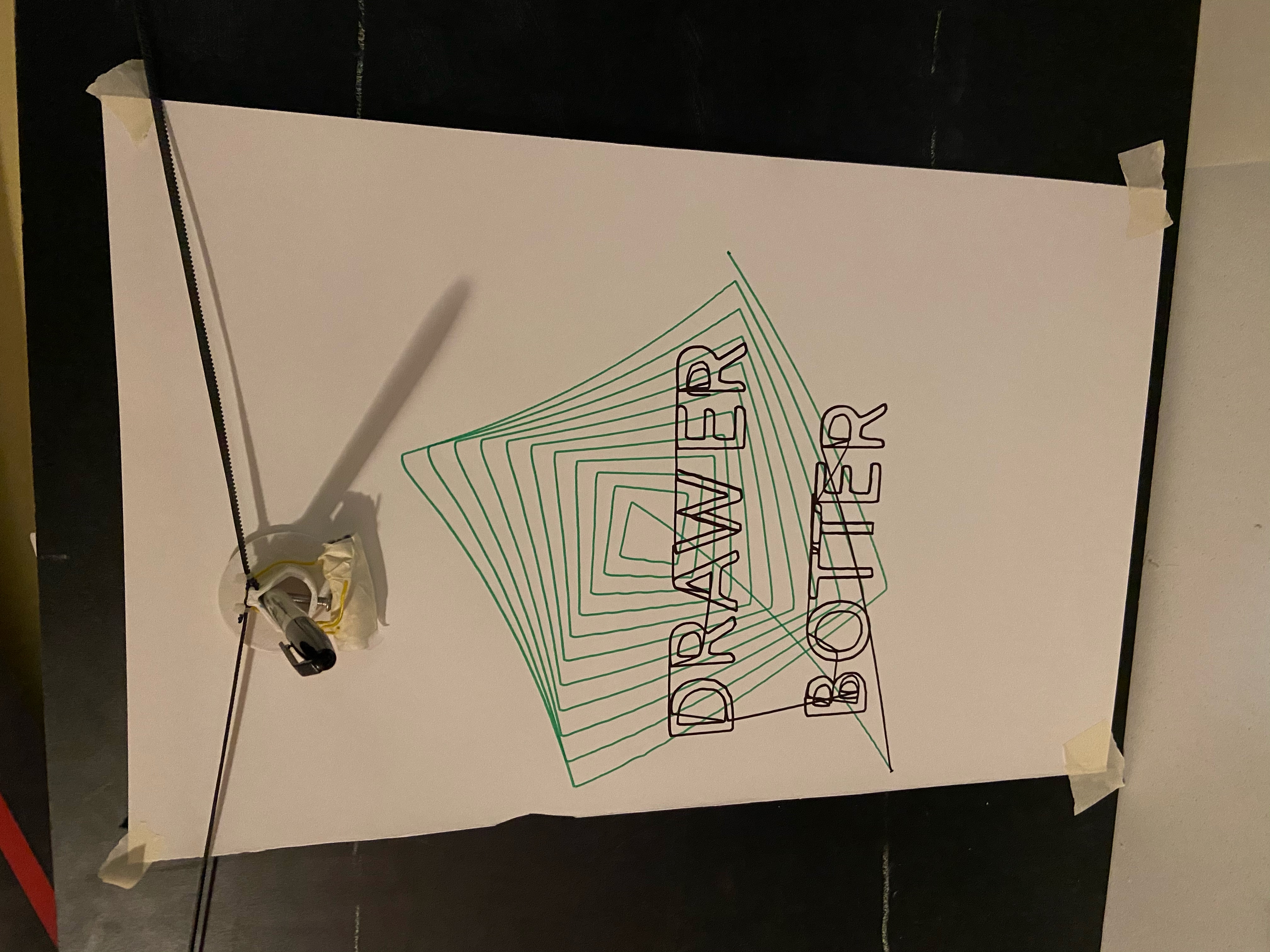
Drawer Botter

Description as a Tweet:
Our project can take in [X, Y] coordinates and draw it onto any surface, with only two stepper motors! Using a polar coordinate system, combined with a variation of CNC gcode, two nema 17 stepper motors can move a pen across a 2D plane, leaving whatever image you desire!
Inspiration:
Having recently designed and build a coreXY 3d printer, we have since been very interested in CNC design, and the many different control systems behind them.
This polar-XY coordinate system is quite similar to how a coreXY 3d printer works, allowing us to take some of our knowledge to design something new. Additionally, the hardware kit combined with our existing tools and hardware helped. However, the most important part was our teams experience with stepper motor drivers, python (to create the gcode), Arduino programming, and CNC kinematics is what truly made this possible.
What it does:
Our project (Drawer Botter) takes a system of [X, Y] coordinates and plots them on (paper, whiteboard, etc.) any surface. This could be used on large whiteboards, small white boards, classroom setting, etc. , and it is very entertaining to watch! See the images attached, but calculating and coordinating the steps the two nema-17 motors must take is quite complicated. It involves not only calculating the current and future length of each of the two belts, but in order to accomplish a straight line both stepper motors must start and finish at ] the exact same time.
For some additional details regarding the project:
- Drawing area of 300x300mm
- 2x nema 17 stepper motors (quarter stepped to 400 steps/revolution)
- Custom 3d printed pen holding gantry - Designed in Fusion 360, went through two different variations of this before coming to our (semi) final design
How we built it:
This project was built with two a4988 stepper drivers, two nema 17 stepper motors, and an Arduino (genuine) uno. Currently the coordinates for the pen to follow are hard coded in, where the Arduino Uno then calculates the change in belt lengths, and number of steps required for both stepper motors to be changed. Similar to "Bresneham's Algorithm", the stepping must be done at a slope (one motor stepping dependently of the other), as a straight line is only possible when both motors start and finish at the exact same time. Then, you have a very pretty, "hand" drawn image of whatever you desire!
Technologies we used:
- C/C++/C#
- Python
- Arduino
- Microcontrollers
- Robotics
- Other Hardware
Challenges we ran into:
Having both stepper motors was one of the largest challenges. Having both stepper motors start and finish each command at the exact same time is necessary for any straight line, this is only possible if the motor with less requires steps steps at a much slower, and sometimes inconsistent rate relative to the higher stepping motor.
Additionally, the pen gantry went through three total iterations. Each one was custom designed in AutoDesk Fusion360, and 3d printed on a custom build 3d printer. This rapid prototyping helped in allowing us to complete this project relatively quickly (1.5 days).
Accomplishments we're proud of:
We are proud of every part of it! However, being able to take a coordinate and move a physical object (pen) to that exact location is the most satisfying. Having both stepper motors start and stop at the exact right time to create a straight line was the most time consuming aspect. However, the physical aspect (drilling holes in the board, mounting stepper motors, getting belts lined up, etc.) also took a large chunk of the time we allotted to this project.
What we've learned:
Stepper motors are complicated, but well worth the effort. Additionally, your first prototype is not likely to work, we went through many iterations of this project very quickly, having to rapidly 3d print the gantry several times, and having to drill the holes for the stepper motor mounting bolt holes far too many times.
What's next:
Next for this project is to get better data to plot! This plotter is only as good as the software and images it has to draw. Additionally, having a serial data transfer (similar to how a CNC machine receives its gcode) could be extremely beneficial.
Built with:
2x Nema 17 stepper motor
2x a4988 stepper motor driver
1x Arduino Uno (from hardware kit)
1x 12v power supply
2x 20t GT2 pulls
2x GT2 belts
1x Custom designed (in Fusion 360) and 3d printed gantry (to hold the pen)
Breadbord, wires, nuts and bolts, markers, board, etc.
Prizes we're going for:
- Best Beginner Hardware Hack
- Funniest Hack
- Best Hardware Hack
Prizes Won
Team Members
Zachary Trani
Jack Chen
